
How bright is it in here, in four LEDs
Four LEDs that light one after another as a room gets brighter. A photoresistor and one quad op amp chip, no code.
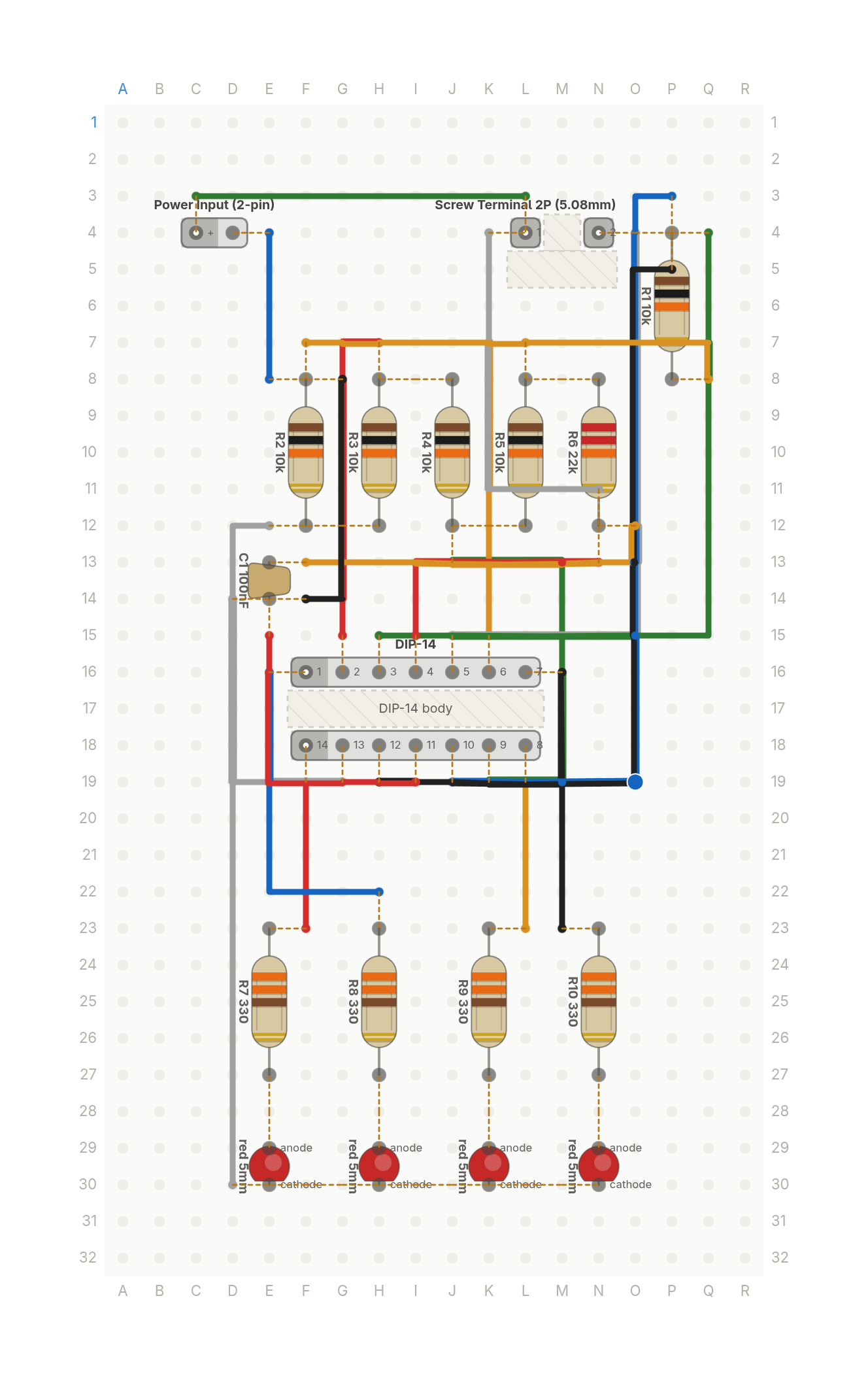
Free build sheet
The parts, every wire with its length and bend points, a bend guide, both sides of the board and checkboxes to track your progress. Print it or keep it open at the bench.
Open the build sheetWhat you need
18 parts on a perfboard 18 × 32 holes, plus hookup wire.
| Qty | Part | Where to buy |
|---|---|---|
| 1 | Ceramic Cap100nF C1 | Buy Ceramic Cap on Amazon |
| 1 | Power Input (2-pin) J1 | |
| 1 | Screw Terminal 2P (5.08mm) J2 | |
| 4 | LEDred 5mm LED1, LED2, LED3, LED4 | Buy LED on Amazon |
| 5 | Resistor (axial)10k R1, R2, R3, R4, R5 | Buy Resistor (axial) on Amazon |
| 1 | Resistor (axial)22k R6 | Buy Resistor (axial) on Amazon |
| 4 | Resistor (axial)330 R7, R8, R9, R10 | Buy Resistor (axial) on Amazon |
| 1 | DIP-14 U1 |
Check every pin against the datasheet of the exact part in your hands before wiring.
As an Amazon Associate I earn from qualifying purchases.
Cut list
21 wires, 787 mm (31.0 in) in total, in the order the build sheet cuts them. Wire numbers match the build sheet. Each length includes 5 mm per end to go through the hole.
| Wire | Colour and net | Length | ||
|---|---|---|---|---|
| 6 | BlackOUT4 M23 → M16 | M23 → M16 | 28mm | Straight |
| 18 | BlackGND G8 → F14 | G8 → F14 | 28mm | 20mm (90°) |
| 12 | BlackSENSE P5 → H19 | P5 → H19 | 66mm | 8mm (90°), 43mm (90°) |
| 17 | BlueGND E8 → E4 | E8 → E4 | 20mm | Straight |
| 5 | BlueOUT2 H22 → E16 | H22 → E16 | 33mm | 13mm (90°) |
| 11 | BlueSENSE P3 → J19 | P3 → J19 | 66mm | 8mm (90°), 48mm (90°) |
| 16 | GreenVCC L3 → C3 | L3 → C3 | 33mm | Straight |
| 4 | GreenT3 J13 → K19 | J13 → K19 | 38mm | 13mm (90°), 28mm (90°) |
| 10 | GreenSENSE Q4 → H15 | Q4 → H15 | 61mm | 33mm (90°) |
| 1 | RedOUT1 F23 → F19 | F23 → F19 | 20mm | Straight |
| 13 | RedVCC N13 → I15 | N13 → I15 | 28mm | 18mm (90°) |
| 19 | RedGND E15 → I19 | E15 → I19 | 30mm | 15mm (90°) |
| 7 | RedT2 H7 → G15 | H7 → G15 | 33mm | 8mm (90°) |
| 15 | WhiteVCC N11 → K4 | N11 → K4 | 35mm | 13mm (90°) |
| 3 | WhiteT1 E12 → G19 | E12 → G19 | 38mm | 8mm (90°), 25mm (90°) |
| 9 | WhiteSENSE O4 → J15 | O4 → J15 | 51mm | 33mm (90°) |
| 21 | WhiteGND D14 → D30 | D14 → D30 | 51mm | Straight |
| 2 | YellowOUT3 L23 → L19 | L23 → L19 | 20mm | Straight |
| 8 | YellowT4 L7 → K15 | L7 → K15 | 33mm | 8mm (90°) |
| 14 | YellowVCC O12 → F13 | O12 → F13 | 35mm | 8mm (90°) |
| 20 | YellowGND F7 → Q8 | F7 → Q8 | 40mm | 33mm (90°) |
About this build
A light meter that answers one question: how bright is it in here? A photoresistor off the board on a screw terminal sits in a divider with a 10k resistor, and that one voltage feeds all four comparators inside an LM324 quad op amp.
A five resistor ladder across the 5V rail, a 22k at the top and four 10k below it, sets thresholds at 0.81V, 1.61V, 2.42V and 3.23V. As the room gets brighter, the LEDs light one after another. The 22k at the top is there for a reason: on 5V the LM324 inputs only work up to about 3.5V, and the bigger top resistor keeps every threshold under that.
Each LED gets its own 330 ohm resistor, so a lit LED keeps the same brightness whether it's alone or the whole bar is on. There's no photoresistor in the PerfBoard catalog, which is why the sensor comes in from off the board.
More builds
See all builds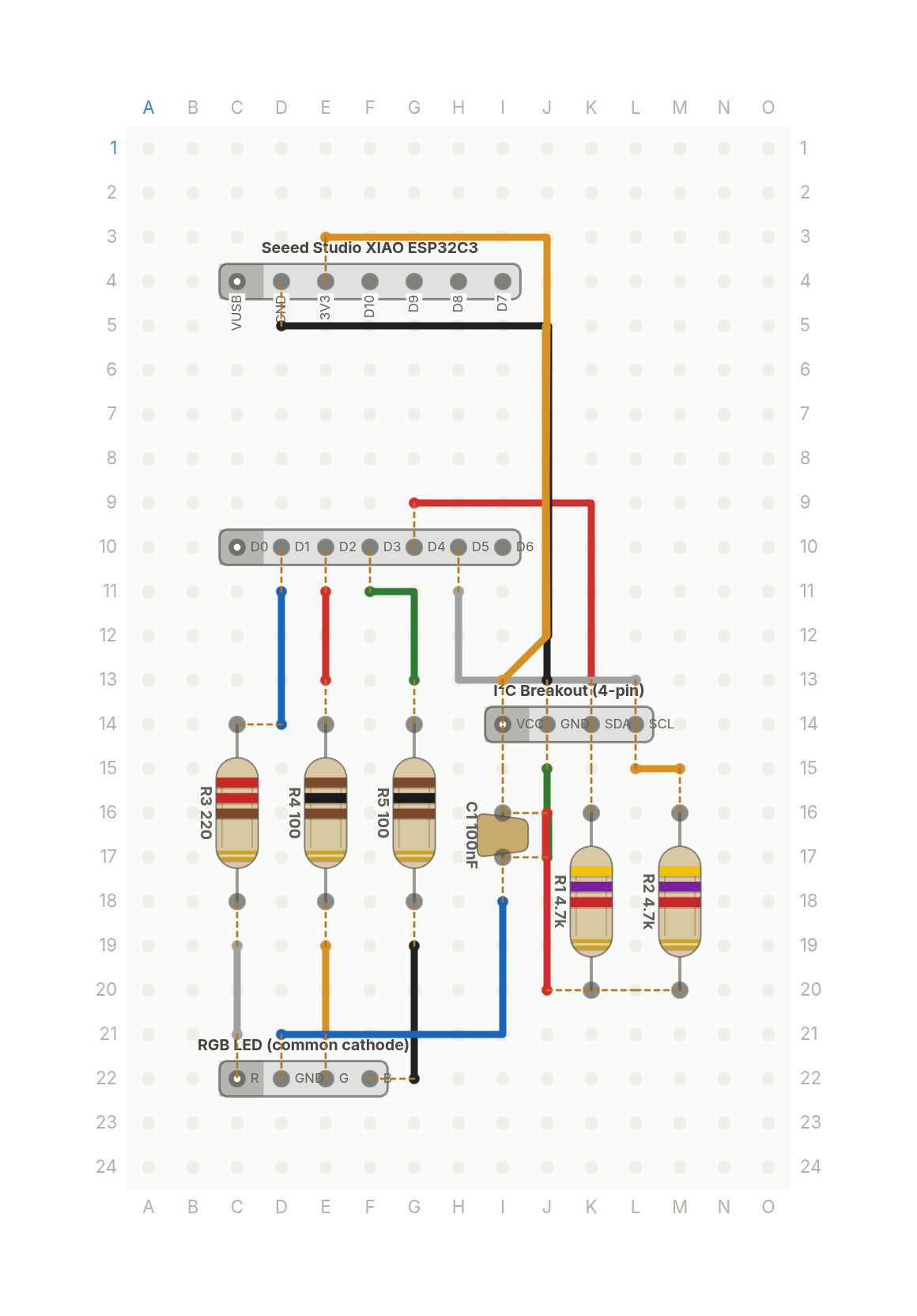 Video
VideoThe whole weather station is three parts
A XIAO ESP32C3 reads a temperature and humidity sensor and shows the reading as a colour on an RGB LED.
9 parts · 14 wires
Sensors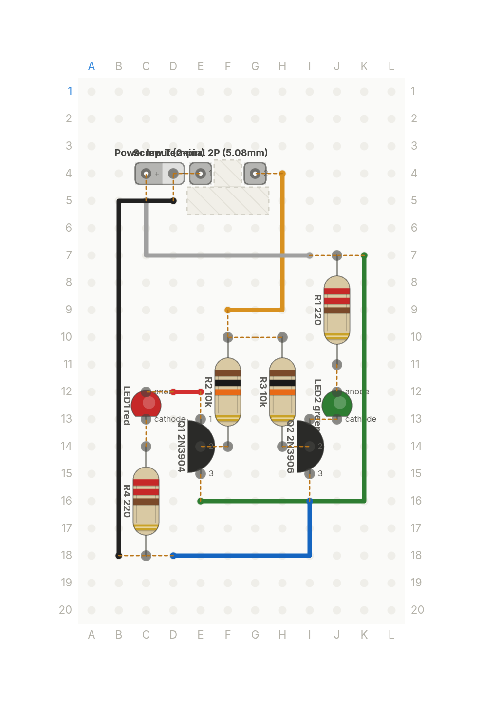 Video
VideoIs that pin high or low? Two transistors tell you
Touch the probe to a 5V logic signal: red means high, green means low, nothing means it's floating. Two transistors, no chip.
10 parts · 6 wires
Tools and test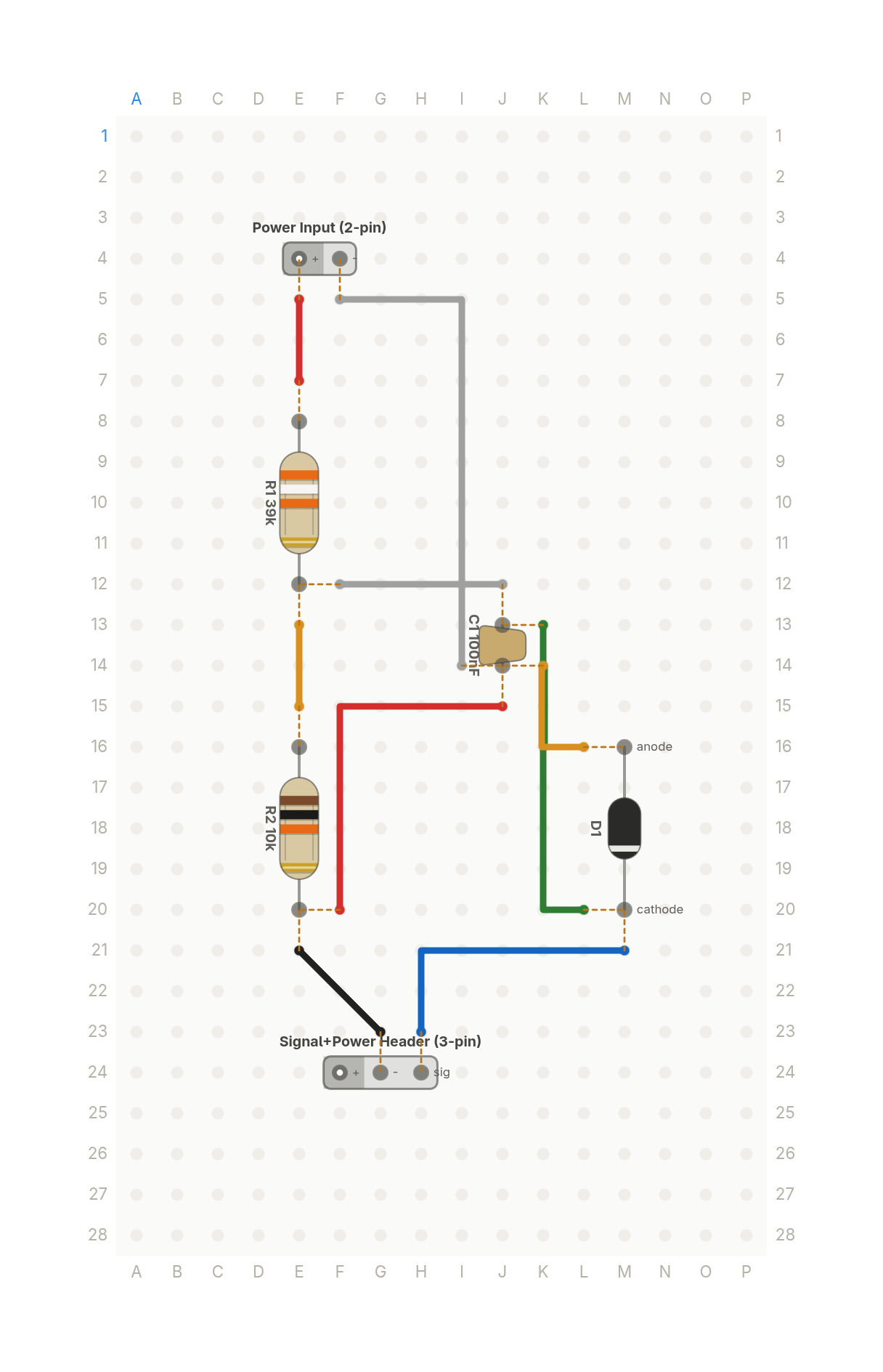 Video
VideoHow your ESP32 reads a 12V battery: the voltage divider
Two resistors scale a 12V battery down to a voltage an ESP32's 3.3V input can read safely, with a zener as a backstop.
6 parts · 9 wires
PowerSensors