
The circuit inside every relay module
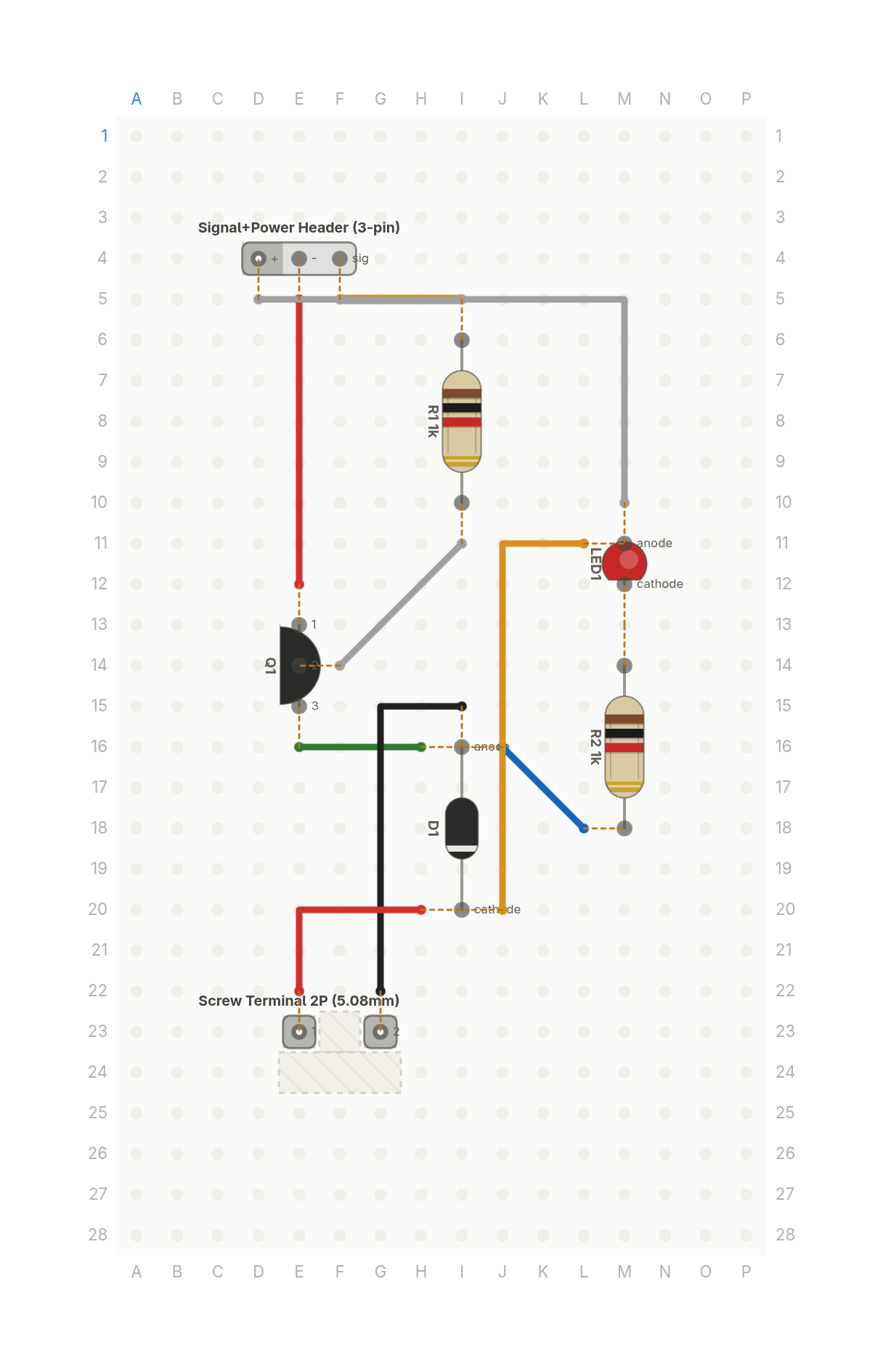
The small circuit inside every hobby relay module: a transistor switch, a base resistor, a flyback diode and a status LED.
Free build sheet
The parts, every wire with its length and bend points, a bend guide, both sides of the board and checkboxes to track your progress. Print it or keep it open at the bench.
Open the build sheetWhat you need
7 parts on a perfboard 16 × 28 holes, plus hookup wire.
| Qty | Part | Where to buy |
|---|---|---|
| 1 | Diode (axial) D1 | |
| 1 | Signal+Power Header (3-pin) J1 | |
| 1 | Screw Terminal 2P (5.08mm) J2 | |
| 1 | LED LED1 | Buy LED on Amazon |
| 1 | NPN Transistor (TO-92) Q1 | Buy NPN Transistor (TO-92) on Amazon |
| 2 | Resistor (axial)1k R1, R2 | Buy Resistor (axial) on Amazon |
Check every pin against the datasheet of the exact part in your hands before wiring.
As an Amazon Associate I earn from qualifying purchases.
Cut list
9 wires, 240 mm (9.4 in) in total, in the order the build sheet cuts them. Wire numbers match the build sheet. Each length includes 5 mm per end to go through the hole.
| Wire | Colour and net | Length | ||
|---|---|---|---|---|
| 6 | BlackCOIL I15 → G22 | I15 → G22 | 33mm | 10mm (90°) |
| 5 | BlueCOIL J16 → L18 | J16 → L18 | 17mm | Straight |
| 4 | GreenCOIL H16 → E16 | H16 → E16 | 18mm | Straight |
| 7 | Red5V H20 → E22 | H20 → E22 | 23mm | 13mm (90°) |
| 1 | RedGND E12 → E5 | E12 → E5 | 28mm | Straight |
| 3 | WhiteBASE I11 → F14 | I11 → F14 | 21mm | Straight |
| 9 | White5V M10 → D5 | M10 → D5 | 46mm | 18mm (90°) |
| 2 | YellowSIG I5 → F5 | I5 → F5 | 18mm | Straight |
| 8 | Yellow5V J20 → L11 | J20 → L11 | 38mm | 28mm (90°) |
About this build
Every hobby relay module hides the same small circuit. A microcontroller pin can't drive a relay coil on its own, so an NPN transistor does it as a low side switch, with a 1k resistor between the signal and the transistor's base.
A flyback diode sits across the coil. When the transistor turns off, the coil's collapsing field tries to spike the voltage, and the diode gives that current somewhere safe to go. A status LED with its own 1k resistor lights when the coil is energised.
The component catalog has no relay, so the coil comes in on a screw terminal. Signal, 5V and ground arrive on a 3 pin header. The transistor is a TO-92 part and lead orders vary, so wire it from the build sheet and the datasheet for your exact part.
More builds
See all builds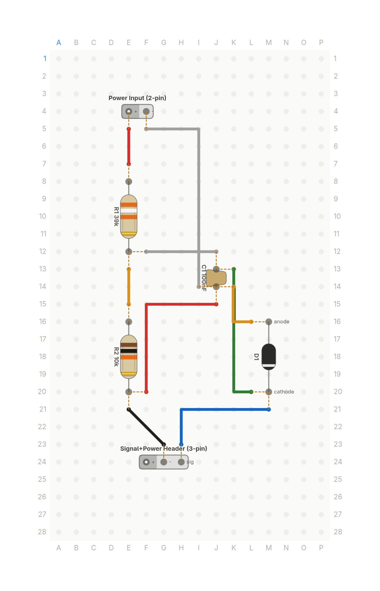 Video
VideoHow your ESP32 reads a 12V battery: the voltage divider
Two resistors scale a 12V battery down to a voltage an ESP32's 3.3V input can read safely, with a zener as a backstop.
6 parts · 9 wires
PowerSensors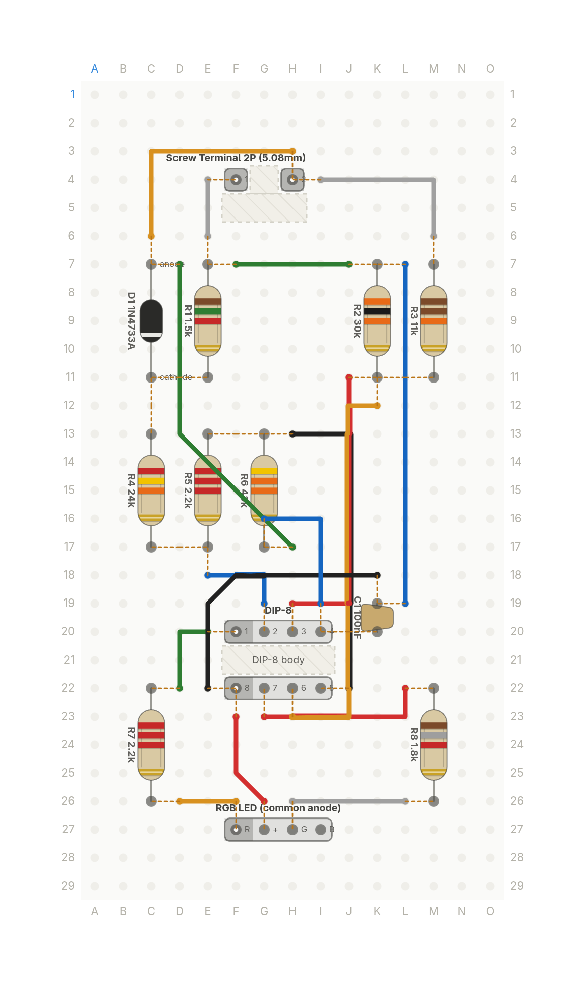 Video
VideoThis LED tells you how dead your battery is
A light for a 12V lead acid battery: green when it's healthy, yellow when it's getting low, red when it's nearly flat.
13 parts · 17 wires
PowerTools and test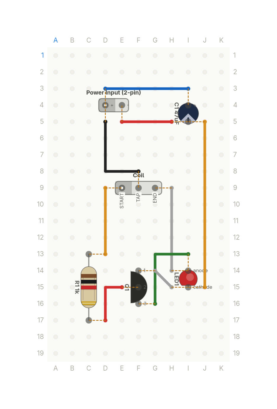 Video
VideoThis lights an LED from a dead battery
One transistor and a hand wound coil that light a white LED from a nearly dead 1V cell. Six parts.
6 parts · 9 wires
LightsPower