
A lie detector from two transistors
A skin resistance meter: a green LED fades and a red one comes up as your fingers sweat. It reads sweat, not lies.
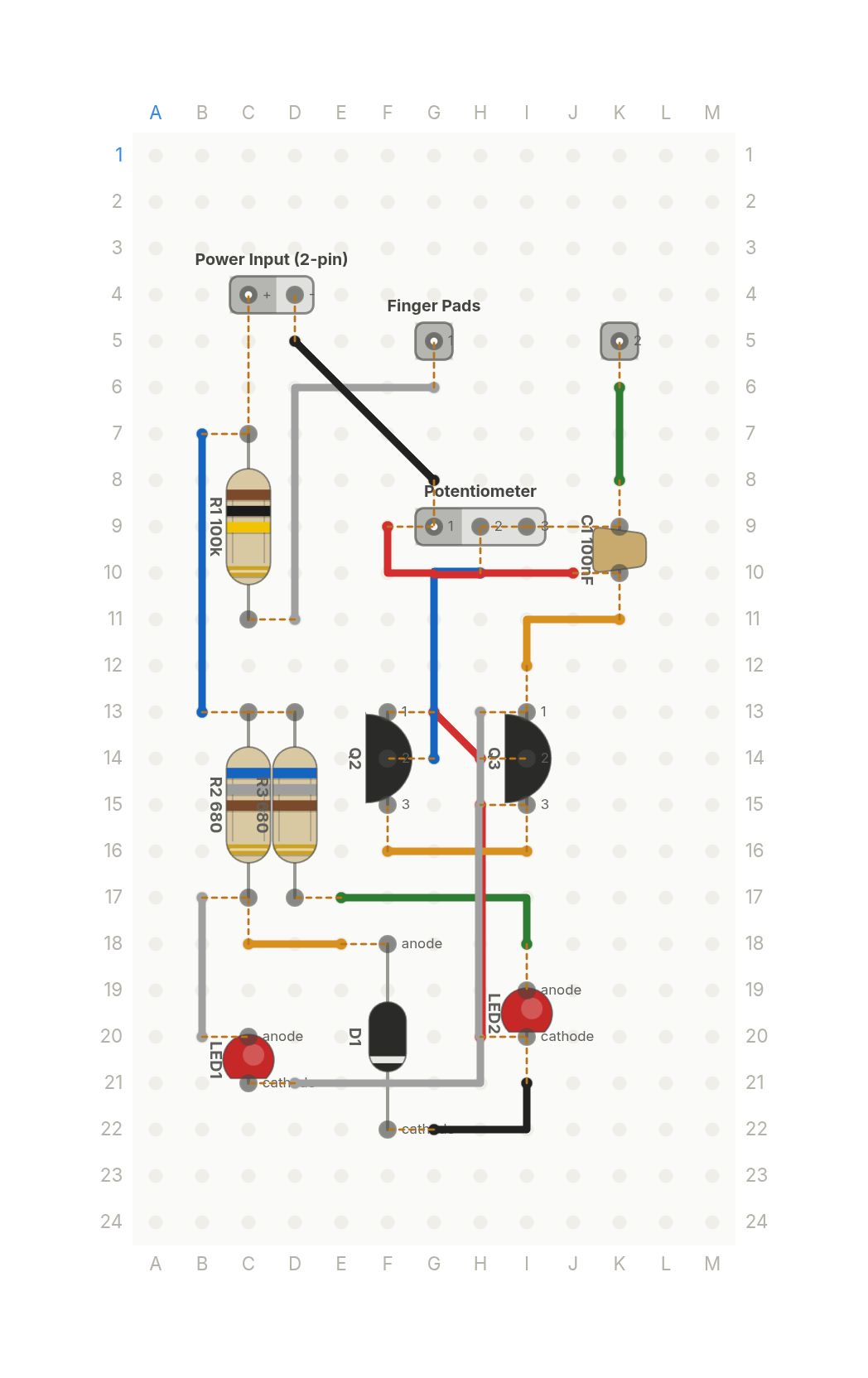
Free build sheet
The parts, every wire with its length and bend points, a bend guide, both sides of the board and checkboxes to track your progress. Print it or keep it open at the bench.
Open the build sheetWhat you need
12 parts on a perfboard 13 × 24 holes, plus hookup wire.
| Qty | Part | Where to buy |
|---|---|---|
| 1 | Ceramic Cap100nF C1 | Buy Ceramic Cap on Amazon |
| 1 | Diode (axial) D1 | |
| 1 | Power Input (2-pin) J1 | |
| 2 | LED LED1, LED2 | Buy LED on Amazon |
| 1 | Potentiometer Q1 | |
| 2 | NPN Transistor (TO-92) Q2, Q3 | Buy NPN Transistor (TO-92) on Amazon |
| 1 | Resistor (axial)100k R1 | Buy Resistor (axial) on Amazon |
| 2 | Resistor (axial)680 R2, R3 | Buy Resistor (axial) on Amazon |
| 1 | Finger Pads U1 |
Check every pin against the datasheet of the exact part in your hands before wiring.
As an Amazon Associate I earn from qualifying purchases.
Cut list
15 wires, 322 mm (12.7 in) in total, in the order the build sheet cuts them. Wire numbers match the build sheet. Each length includes 5 mm per end to go through the hole.
| Wire | Colour and net | Length | ||
|---|---|---|---|---|
| 6 | BlackSINK G22 → I21 | G22 → I21 | 18mm | 10mm (90°) |
| 12 | BlackGND D5 → G8 | D5 → G8 | 21mm | Straight |
| 11 | BlueSENSE H10 → G14 | H10 → G14 | 23mm | 8mm (90°) |
| 5 | BlueVCC B7 → B13 | B7 → B13 | 25mm | Straight |
| 10 | GreenSENSE K6 → K8 | K6 → K8 | 15mm | Straight |
| 4 | GreenRED E17 → I18 | E17 → I18 | 23mm | 15mm (90°) |
| 1 | RedDARL G13 → H14 | G13 → H14 | 14mm | Straight |
| 7 | RedSINK H20 → H15 | H20 → H15 | 23mm | Straight |
| 13 | RedGND F9 → J10 | F9 → J10 | 23mm | 8mm (90°) |
| 3 | WhiteGREEN B17 → B20 | B17 → B20 | 18mm | Straight |
| 9 | WhitePAD D11 → G6 | D11 → G6 | 30mm | 18mm (90°) |
| 15 | WhiteGND H13 → D21 | H13 → D21 | 40mm | 25mm (90°) |
| 2 | YellowGREEN E18 → C18 | E18 → C18 | 15mm | Straight |
| 8 | YellowSINK I16 → F16 | I16 → F16 | 18mm | Straight |
| 14 | YellowGND K11 → I12 | K11 → I12 | 18mm | 10mm (90°) |
About this build
The classic hobby lie detector is a skin resistance meter. Your finger bridges two pads, and when you sweat, your skin conducts a little better, so a little more current reaches two 2N3904 transistors wired as a Darlington pair. They multiply that current thousands of times.
A green LED is on while you're calm. As your skin resistance falls, the red LED comes up and the green one fades. A 1M trimmer sets the sensitivity and a 100k resistor sits in series with the pads. The rest is a 100nF cap, two 680 ohm resistors and a 1N4148 diode. The parts library has no finger pads, so the video draws them in the Footprint Editor first.
It reads sweat, not lies, and it can't tell whether anyone's telling the truth, so treat it as a toy. Power it from a 9V battery only. Never connect anything you touch to mains power or to a mains adapter.
More builds
See all builds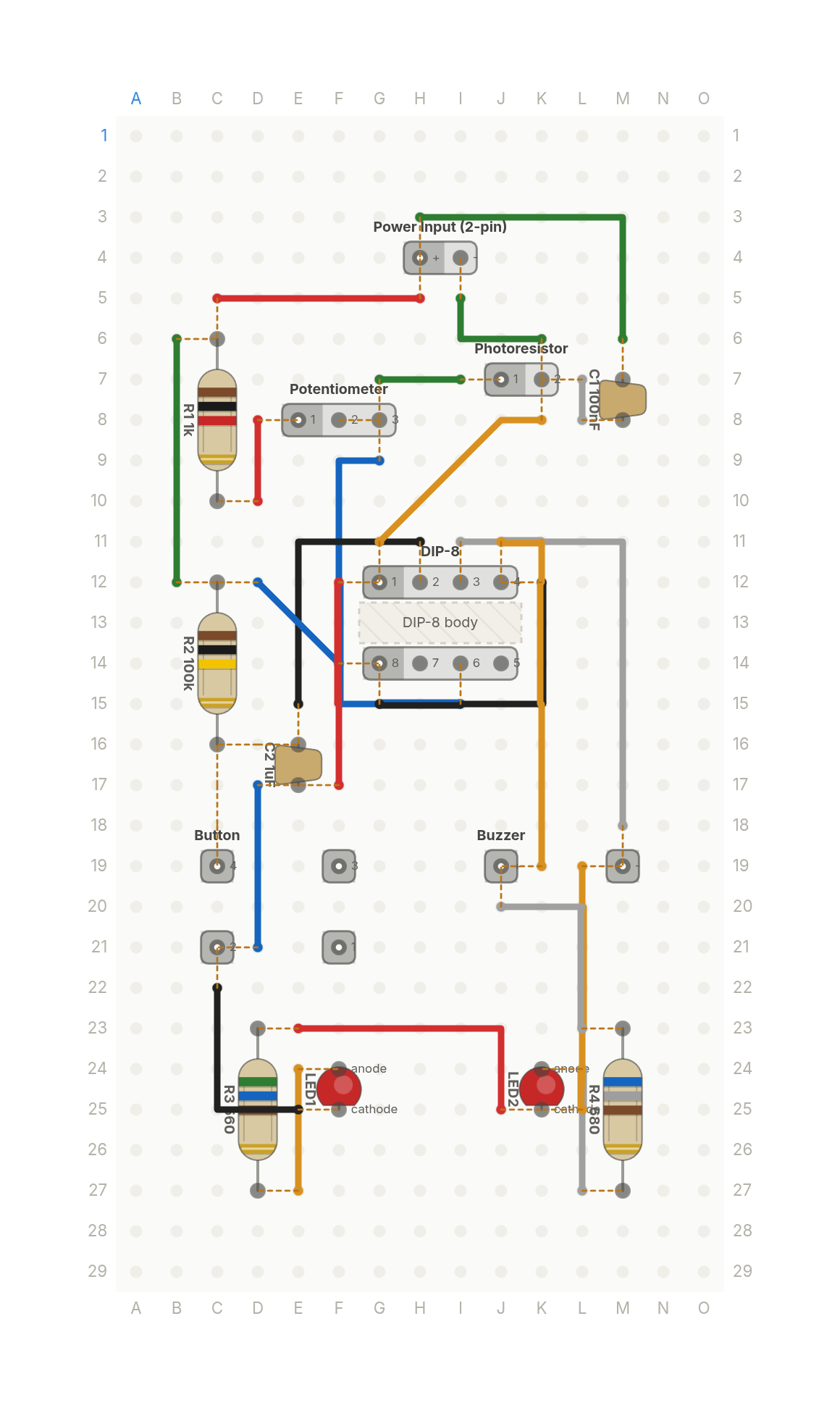 Video
VideoA laser tripwire alarm, like in the movies
Break the laser beam and a red LED and buzzer latch on until you press reset. A photoresistor and one 555 timer.
14 parts · 22 wires
SensorsGames and toys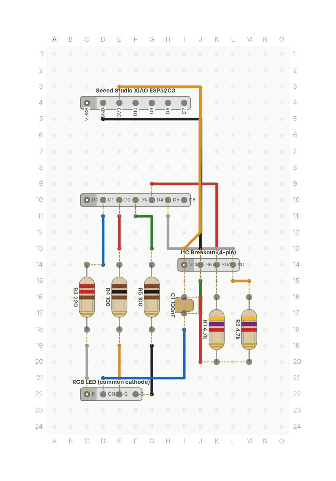 Video
VideoThe whole weather station is three parts
A XIAO ESP32C3 reads a temperature and humidity sensor and shows the reading as a colour on an RGB LED.
9 parts · 14 wires
Sensors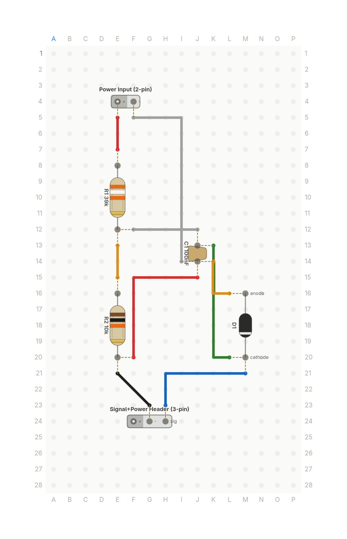 Video
VideoHow your ESP32 reads a 12V battery: the voltage divider
Two resistors scale a 12V battery down to a voltage an ESP32's 3.3V input can read safely, with a zener as a backstop.
6 parts · 9 wires
PowerSensors