
Is that pin high or low? Two transistors tell you
Touch the probe to a 5V logic signal: red means high, green means low, nothing means it's floating. Two transistors, no chip.
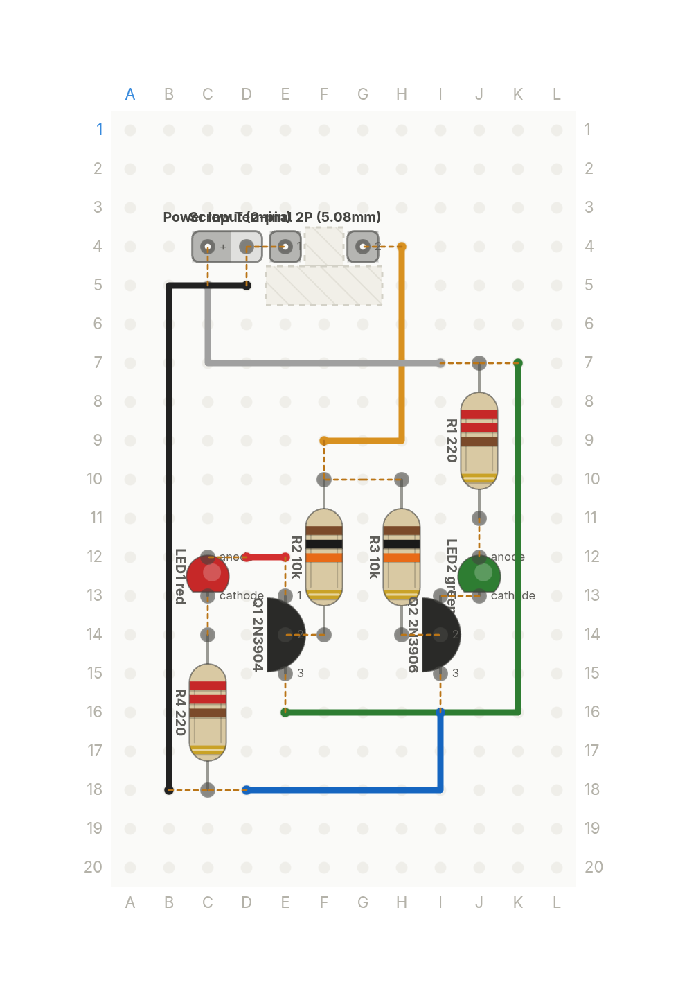
Free build sheet
The parts, every wire with its length and bend points, a bend guide, both sides of the board and checkboxes to track your progress. Print it or keep it open at the bench.
Open the build sheetWhat you need
10 parts on a perfboard 12 × 20 holes, plus hookup wire.
| Qty | Part | Where to buy |
|---|---|---|
| 1 | Power Input (2-pin) J1 | |
| 1 | Screw Terminal 2P (5.08mm) J2 | |
| 1 | LEDred LED1 | Buy LED on Amazon |
| 1 | LEDgreen LED2 | Buy LED on Amazon |
| 1 | NPN Transistor (TO-92)2N3904 Q1 | Buy NPN Transistor (TO-92) on Amazon |
| 1 | PNP Transistor (TO-92)2N3906 Q2 | |
| 2 | Resistor (axial)220 R1, R4 | Buy Resistor (axial) on Amazon |
| 2 | Resistor (axial)10k R2, R3 | Buy Resistor (axial) on Amazon |
Check every pin against the datasheet of the exact part in your hands before wiring.
As an Amazon Associate I earn from qualifying purchases.
Cut list
6 wires, 195 mm (7.7 in) in total, in the order the build sheet cuts them. Wire numbers match the build sheet. Each length includes 5 mm per end to go through the hole.
| Wire | Colour and net | Length | ||
|---|---|---|---|---|
| 6 | BlackGND B18 → D5 | B18 → D5 | 48mm | 38mm (90°) |
| 5 | BlueGND D18 → I16 | D18 → I16 | 28mm | 18mm (90°) |
| 4 | GreenVCC K7 → E16 | K7 → E16 | 48mm | 28mm (90°) |
| 1 | RedRED_A E12 → D12 | E12 → D12 | 13mm | Straight |
| 3 | WhiteVCC I7 → C5 | I7 → C5 | 30mm | 20mm (90°) |
| 2 | YellowPROBE F9 → H4 | F9 → H4 | 28mm | 10mm (90°) |
About this build
A logic probe with no chip in it. Touch the probe to a 5V logic signal and it tells you what's there: red for high, green for low, and nothing at all when the probe is floating.
A 2N3904 NPN and a 2N3906 PNP transistor do the reading, each with a 10k base resistor and an indicator LED in its emitter leg. The two LED forward voltages stack up inside the base loop, and that's what keeps both lights off when the probe touches nothing.
Power comes from the circuit under test through a 2 pin input, and a 2 pin screw terminal takes the probe wire and the ground clip. Each LED gets a 220 ohm resistor.
More builds
See all builds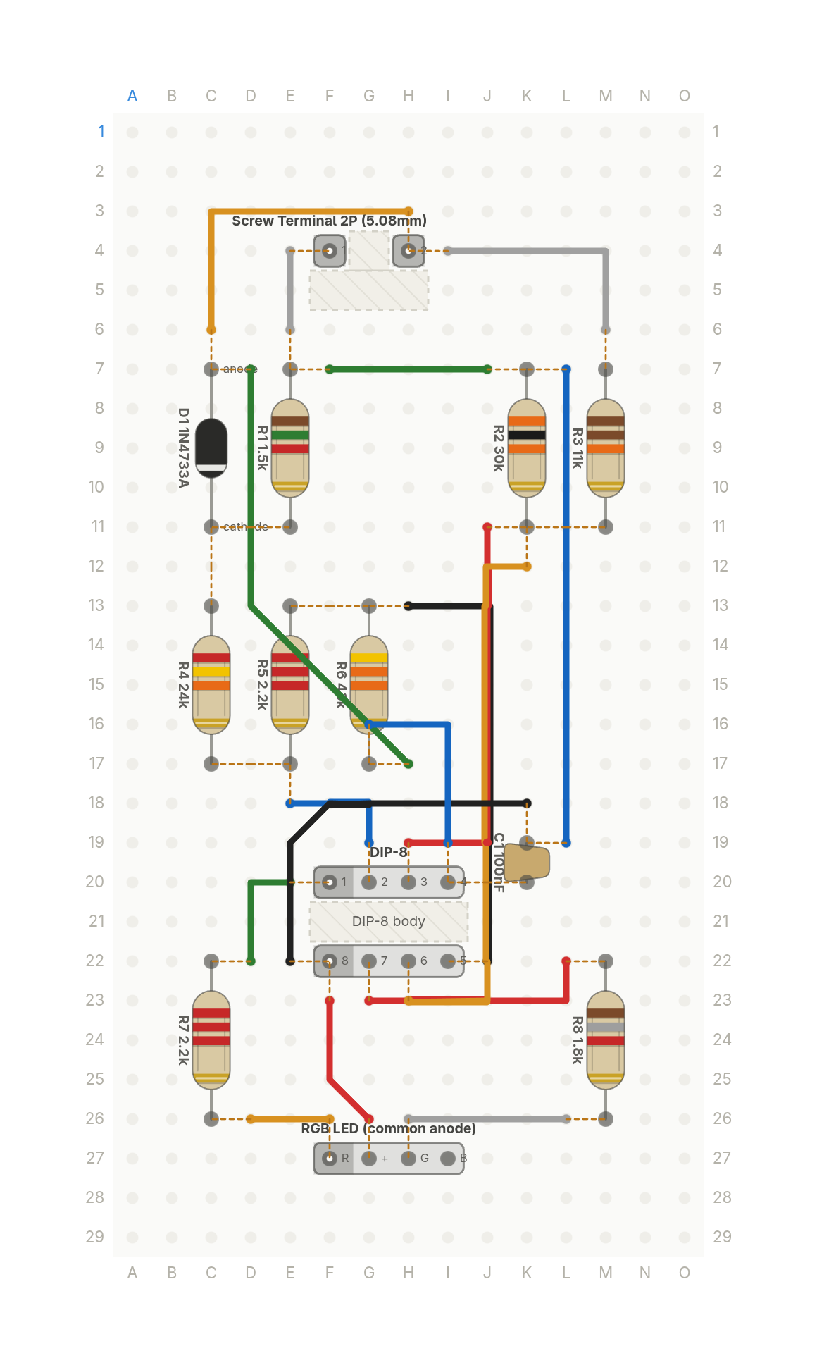 Video
VideoThis LED tells you how dead your battery is
A light for a 12V lead acid battery: green when it's healthy, yellow when it's getting low, red when it's nearly flat.
13 parts · 17 wires
PowerTools and test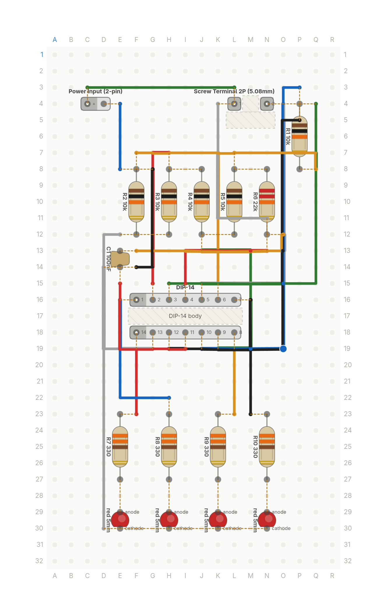 Premieres Oct 31
How bright is it in here, in four LEDs
Four LEDs that light one after another as a room gets brighter. A photoresistor and one quad op amp chip, no code.
18 parts · 21 wires
SensorsTools and test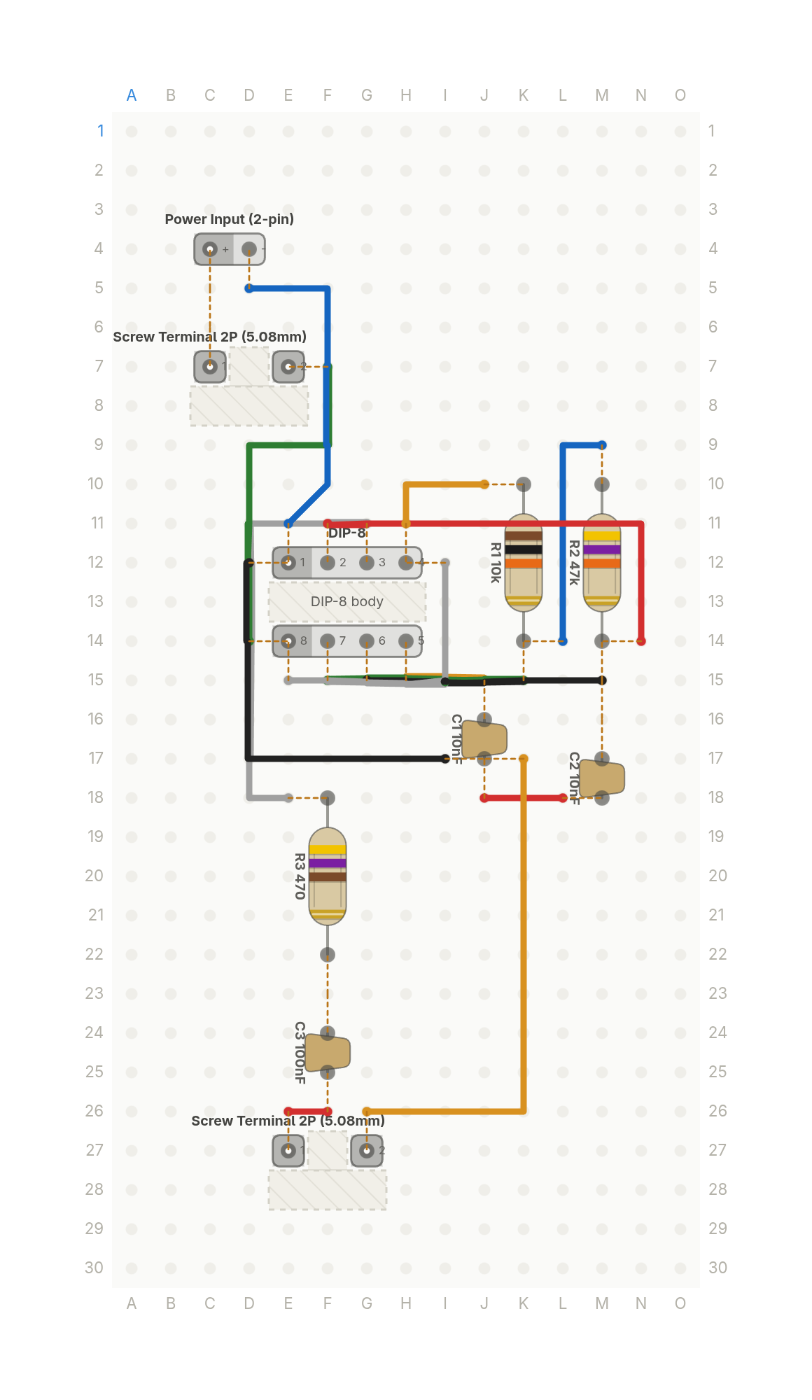 Premieres Nov 10
The tool every electronics bench has, from one chip
Touch two probes across anything that conducts and it beeps. A bench continuity tester from one 555 timer and a piezo.
10 parts · 14 wires
Tools and test