
From breadboard to perfboard to PCB: one sensor, three boards
This is one build, photographed at three stages. It's a battery-powered LoRa temperature sensor for agricultural temperature monitoring: an ESP32, a LoRa radio, temperature probes on a long cable and AA cells in a sealed box.
It started on a breadboard, moved to perfboard and ended as a custom PCB. Each board answered a different question. Here's what each one was for, and the one mistake that ended up on a PCB.
Stage 1: the breadboard
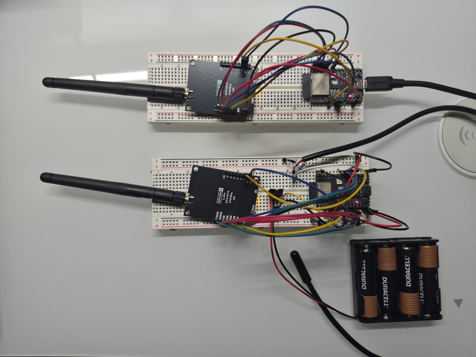
Each breadboard has an ESP32 dev board and a 915 MHz LoRa breakout with a whip antenna. The top one runs from USB. The bottom one runs from four AA cells and has a temperature probe on a cable.
It's a tangle of jumper wires, and that's fine. The breadboard has one job: prove the circuit and find the wiring.
There were lots of iterations at this stage. I revised the wire placements to avoid strapping pins and to keep everything close together. On a breadboard that costs seconds. Pull the jumper, move it, try again.
Strapping pins are pins the ESP32 reads at power-up to decide how to boot, so anything wired to one can stop the board from starting. Check your module's datasheet for which pins they are, and route around them.
The radio module on these breadboards ended up being a bit more complicated than I would have liked. So I found an alternative radio that was easier to integrate, smaller and cheaper. That's why the radio in the next photos is a different board.
Nothing here is meant to last. What you carry forward is the list of connections that worked. Write it down before you take anything apart.
Stage 2: the perfboard
Once I had everything worked out, I moved to a perfboard build. It's the same circuit with the new radio. The questions are new: where does each part sit, and does it all fit in the box?
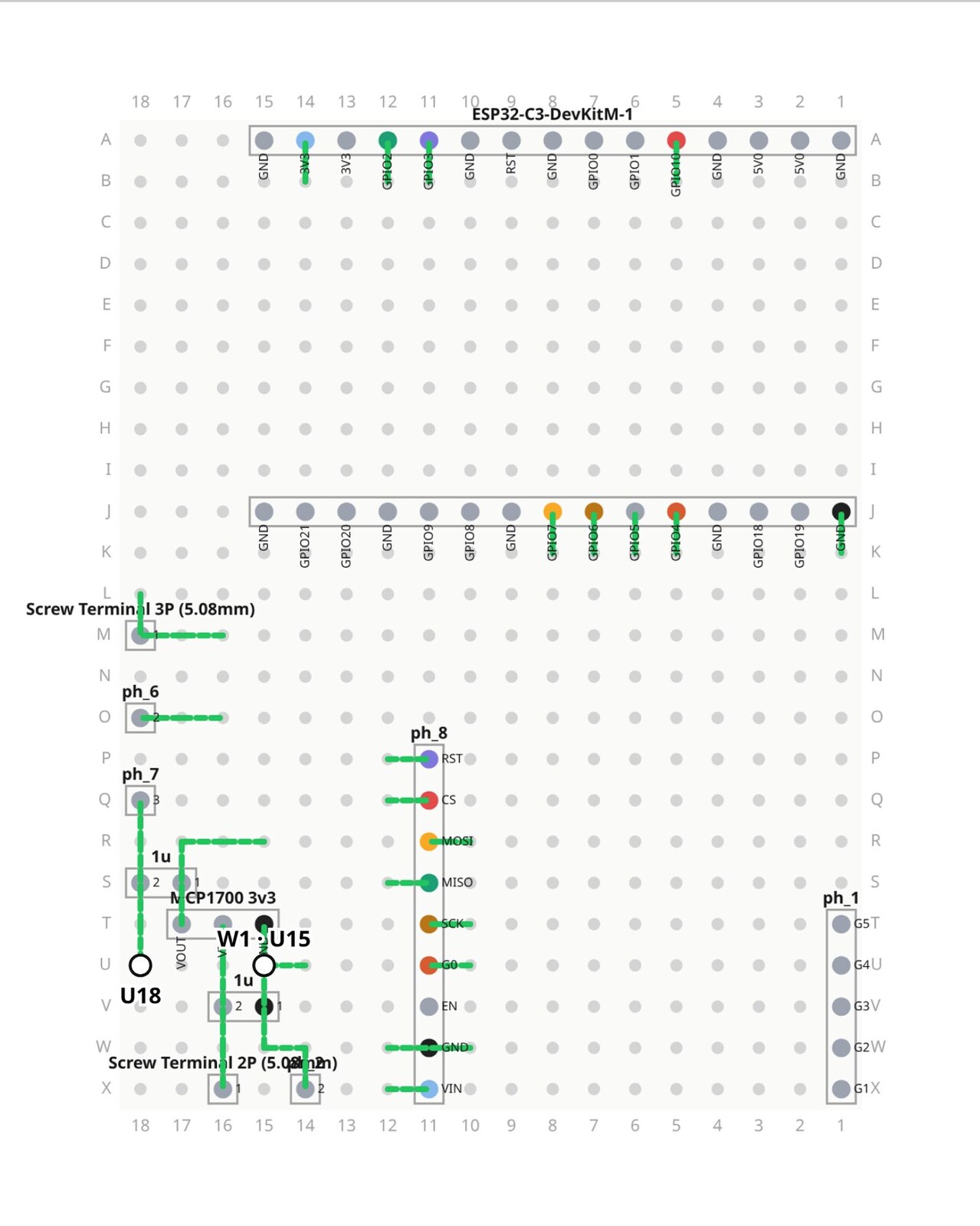
I laid this board out in PerfBoard before I soldered it.
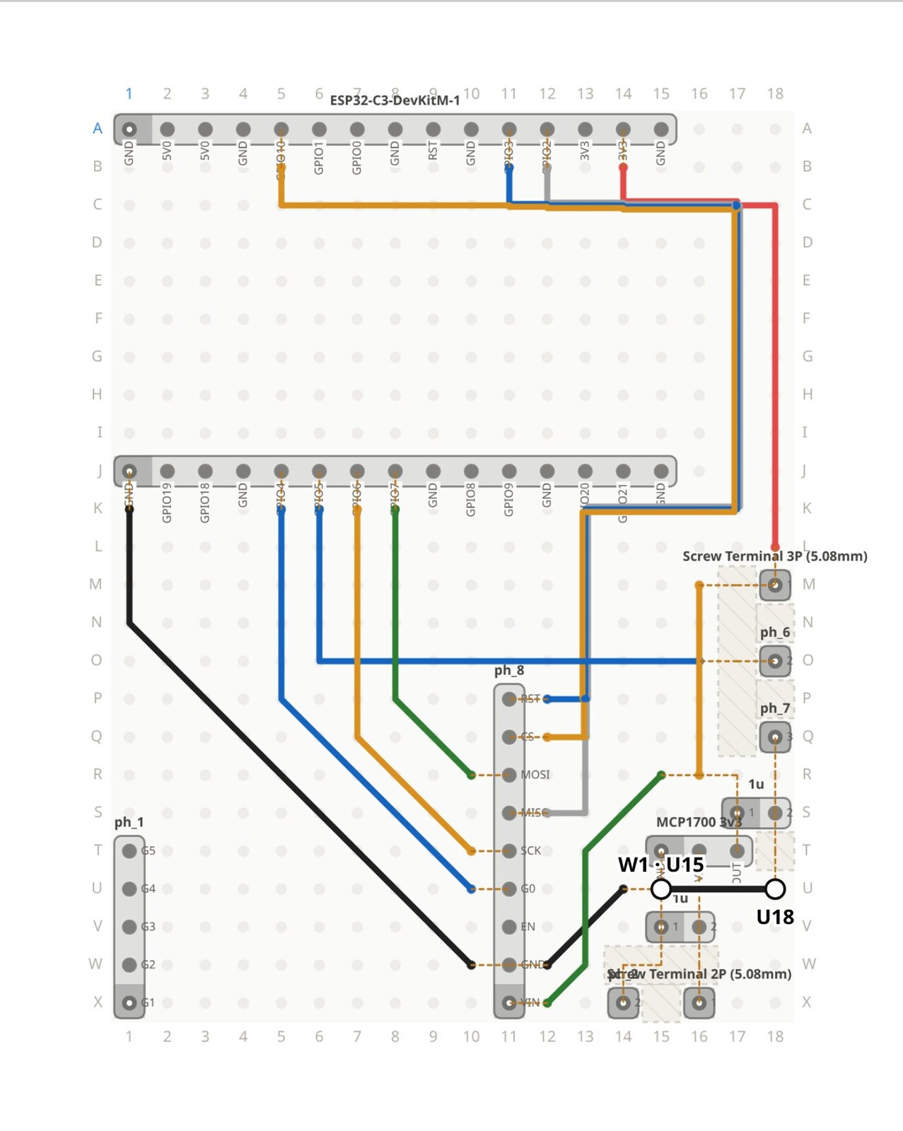
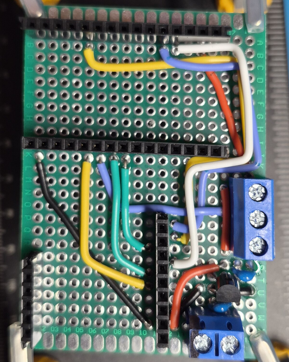
A few things changed on the way over from the breadboard.
- Sockets for the modules. The dev board and the radio plug into socket headers. They unplug again, so a dead module is a swap and not a rework job.
- Screw terminals for anything that leaves the board. The probe and battery wires need a connection that holds and that you can undo with a screwdriver.
- Solid-core wire cut to length. Each wire lies flat and has its own color. Compare that with the loops in the first photo.
- A few small parts soldered straight in. A TO-92 part and some small capacitors. Check the datasheet for the pinout before you solder a part like that.
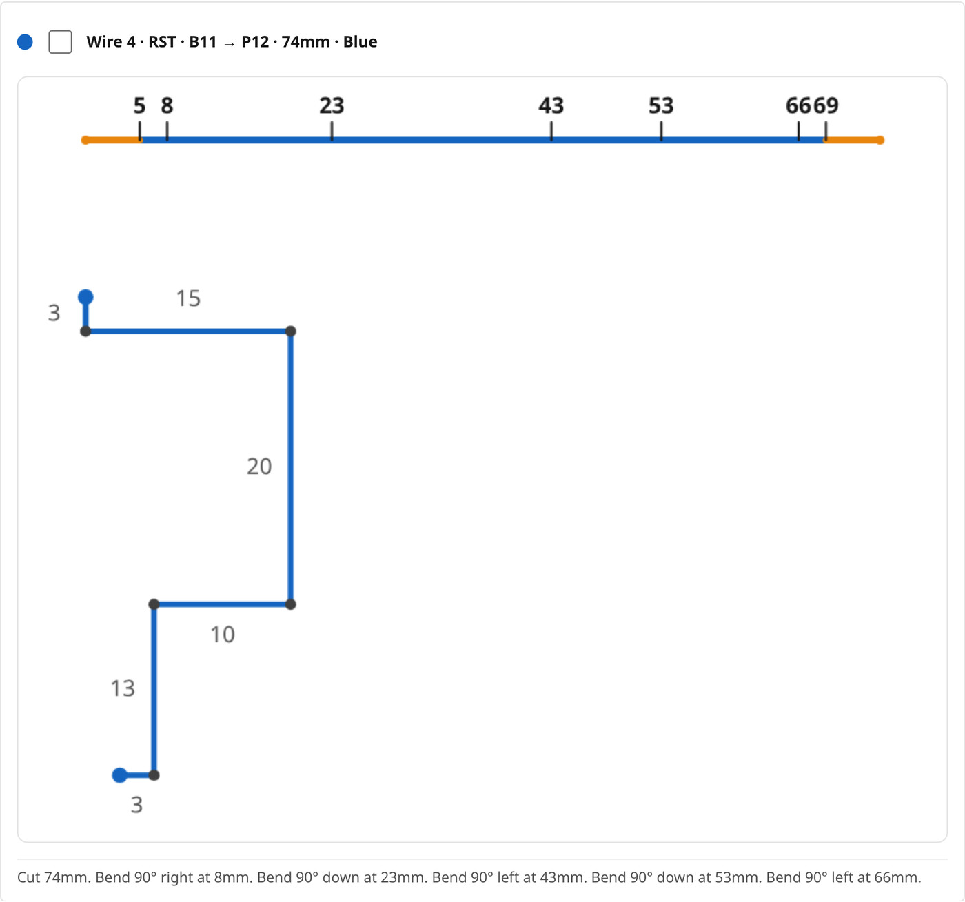
PerfBoard's cut sheet lists each wire's length and bend points. I trust those lengths, so I cut and bend every wire before I assemble and solder anything. It saves me a lot of time. The full cut sheet is part of Pro.
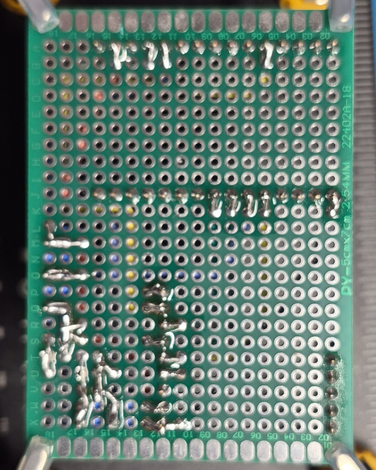
Underneath, a solder bridge joins each wire end to its pin. You solder from the back, where left and right are swapped. So the build guide draws the board flipped, with the bridges marked.
Then the box.
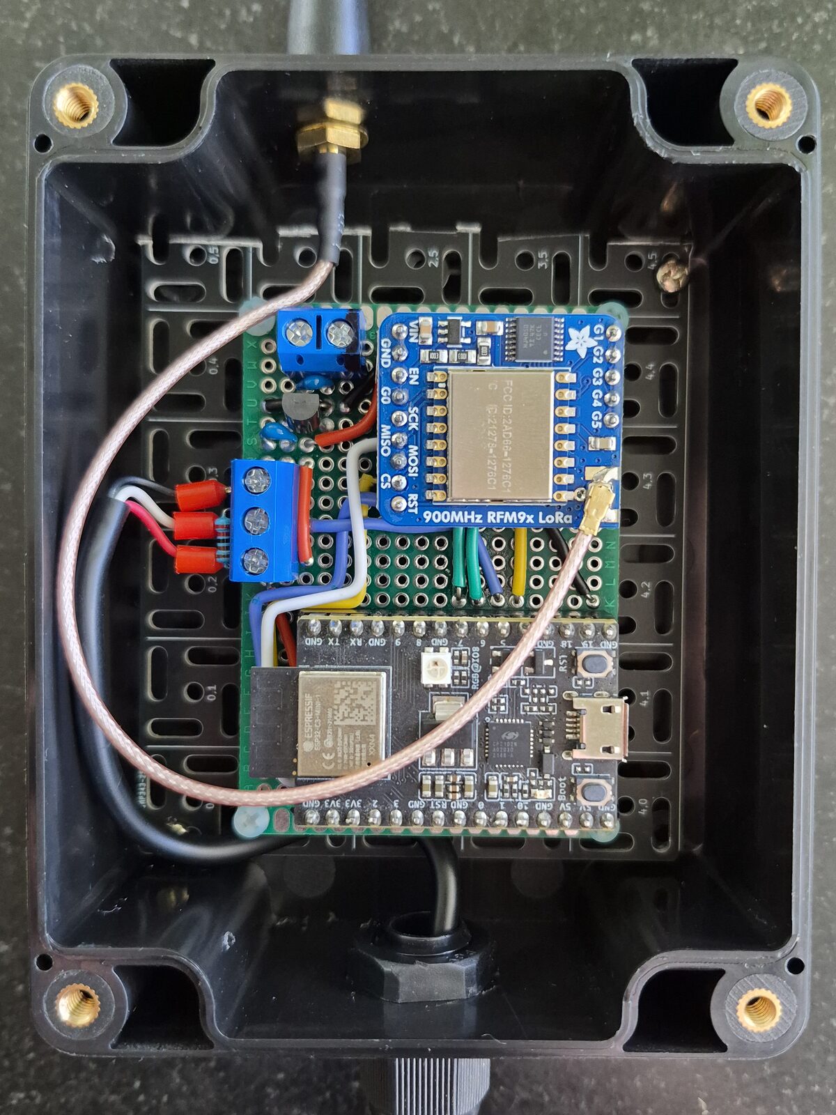
The perfboard is screwed to the enclosure's mounting plate. A thin coax pigtail runs from the radio to an antenna connector in the wall. The probe cable comes in through a cable gland, and its wires end in ferrules in the screw terminal.
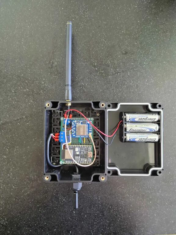
This is the part a breadboard can't tell you. Does the lid close over a dev board standing on sockets? Does the coax reach the connector without a sharp bend? Where do the batteries go? You only find out with the real board in the real box.
Why build the perfboard before the PCB
You could go from the breadboard straight to a PCB. I wouldn't.
A mistake on perfboard costs a desoldered wire. A mistake on a PCB is in every copy, and the fix is a new order and another wait. The perfboard proves the layout and the mechanical fit while a change is still cheap.
Once I was happy with the layout and how it worked, I designed the PCB.
Stage 3: the PCB
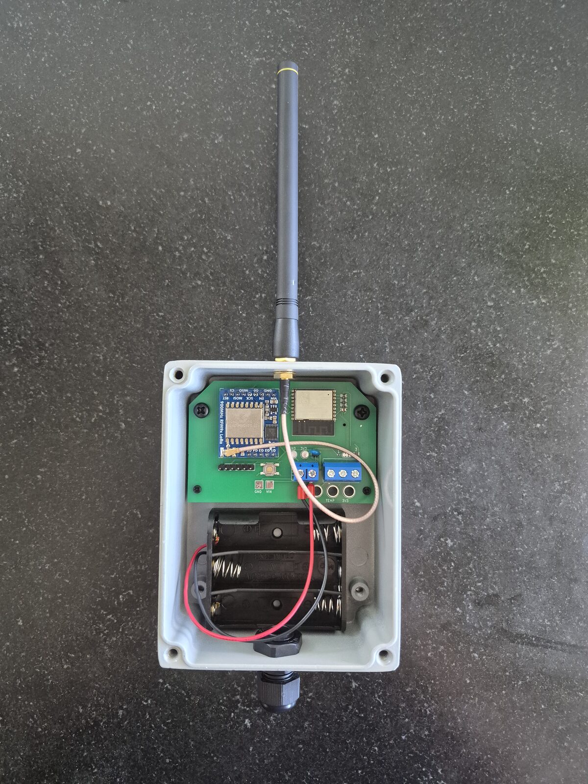
The dev board is gone, and the ESP32 module is soldered straight onto the PCB. There are no hand-cut wires between parts. Every connector has a printed label. The radio is still a separate breakout, and the screw terminals are still there for the battery and the probes.
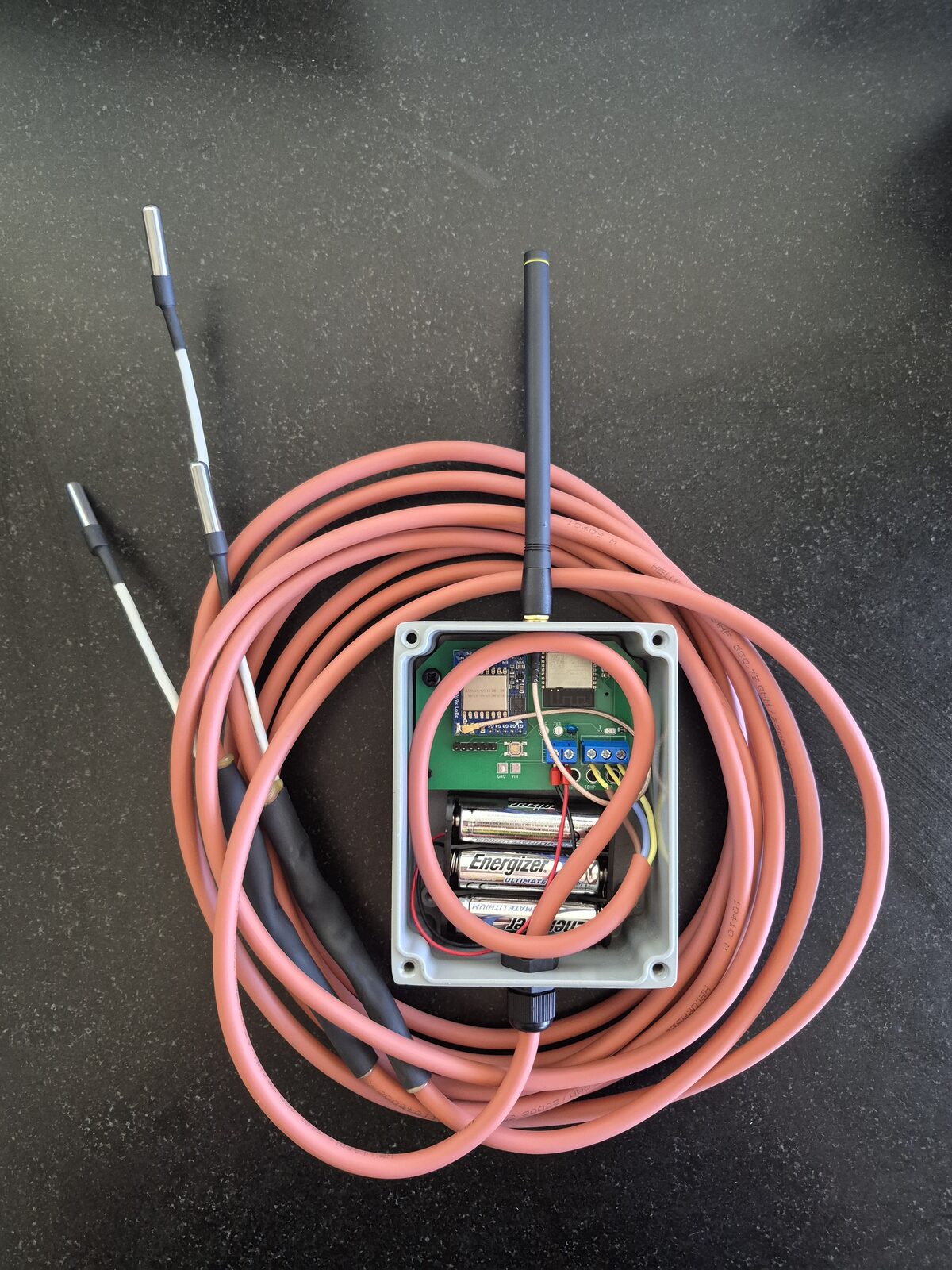
It looks done. It wasn't.
This green version was missing a capacitor on the voltage regulator. The result was that it drew more current from the batteries than expected. On a sensor that has to run from AA cells, that's the number that matters most.
That's the PCB trade in one mistake. A missing part on perfboard is one more part to solder in. A mistake in a PCB design is in every board of the batch.
The final version had everything fixed, and battery life went out to over 2 years.
The lesson I'd pass on: a regulator's datasheet says which capacitors it needs. Read it, and check your schematic against it before you order boards.
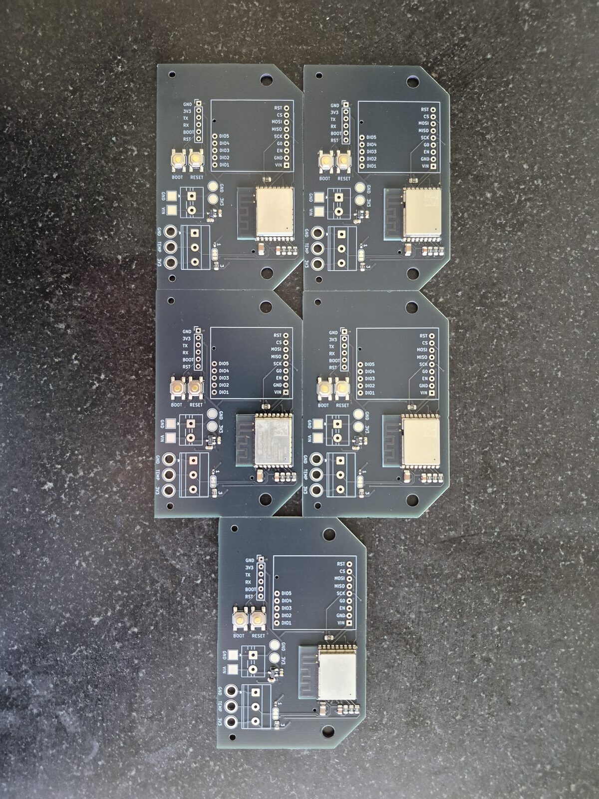
I went on to order 10 custom PCBs. This is what a PCB buys you: repeatability. Every connection is copper laid down by the factory, so board ten is wired the same as board one. Building a unit means soldering parts in, not cutting and routing every wire by hand.
What it costs is the CAD work, the wait, and the chance that a mistake is copied onto every board. That trade only pays when you need copies.
Three boards, three questions
- Breadboard: does the circuit work, and what's the wiring?
- Perfboard: does the layout work, and does it fit the box?
- PCB: can I make many of them, all the same?
You don't have to reach the third one. If you need one sensor, a perfboard in a box is a finished product.
The step that's easiest to rush is the middle one. The circuit is already proven, so the mistakes left are layout mistakes: a wire one hole off, a terminal block that collides with a socket, a board two holes too wide for the mounting plate. Plan that stage on a grid before you solder.
More articles
- What is perfboard? A beginner's guide to building on one
What perfboard is, the types (pad-per-hole, stripboard, breadboard-pattern), what you need to build on one, and how first builds go wrong.
- Breadboard vs perfboard vs stripboard vs PCB: which should you use?
What breadboards, perfboard, stripboard and custom PCBs are each good for, the real trade-offs, and which one to pick for your build.
Plan your next board on the grid before you solder, or start from one of the builds.