
What is perfboard? A beginner's guide to building on one
Perfboard is a thin board full of holes on a 0.1 inch (2.54 mm) grid. You push component leads through the holes, solder them on the back, and make the connections between them yourself. It's how a circuit that works on a breadboard becomes something you can screw into a box and keep.
The name is short for perforated board. You'll also see "perf board", "protoboard" and "prototyping board". Same thing.
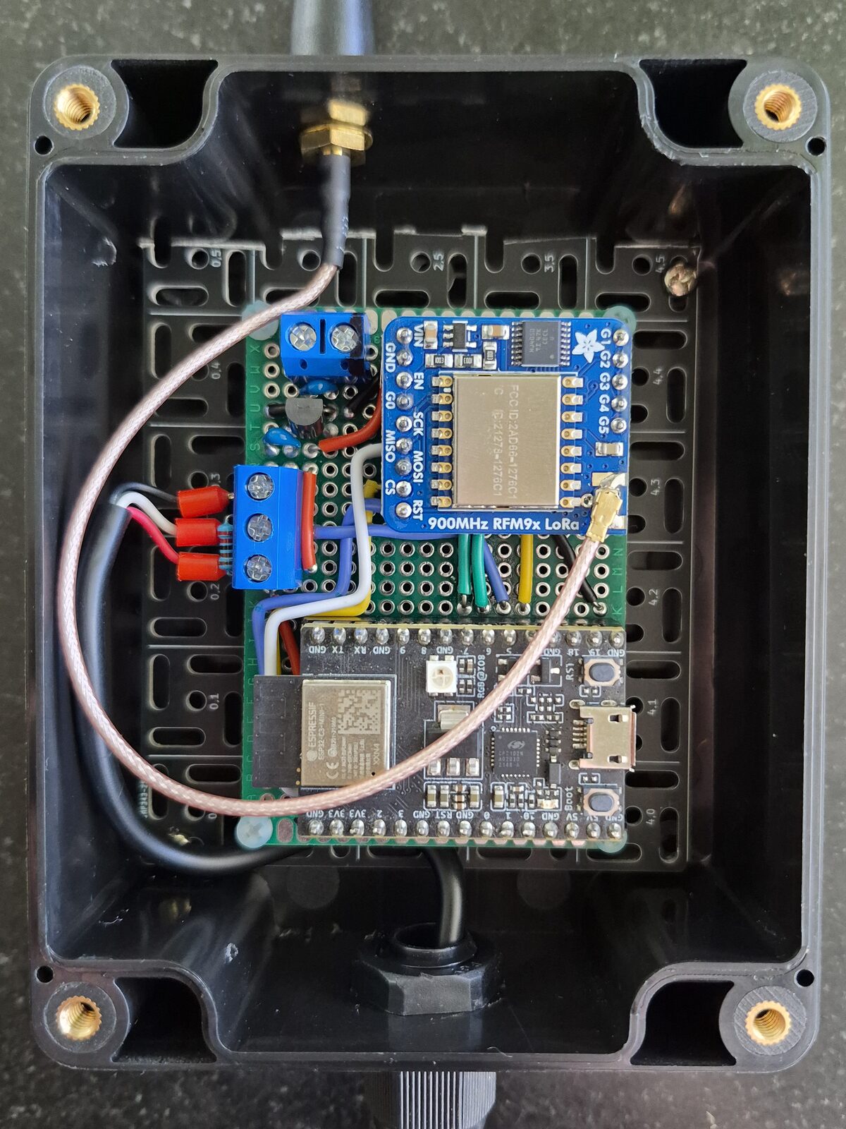
A breadboard proves the circuit. Perfboard makes it permanent. Everything is soldered, so you can drop it, mount it or ship it and it still works. It fits one-offs best: a sensor node, a guitar pedal, an adapter between two modules. No design software, no waiting on a factory.
The types, and how each one connects holes
"Perfboard" covers a few different boards. The difference is the copper: what's already connected before you start.
| Type | Copper | What connects the holes |
|---|---|---|
| Bare board | None | Nothing. The board only holds the parts. |
| Pad-per-hole | One pad around each hole | Nothing. Every pad is on its own. |
| Stripboard | Long parallel strips | Every hole along a strip is joined. |
| Breadboard-pattern | Short strips plus power rails | The same groups as a solderless breadboard. |
Pad-per-hole is what most people mean by perfboard. Every connection is yours to make.
Stripboard gives you connections for free, and you cut the strip where you don't want one. Veroboard is a brand name for stripboard. Same board.
Breadboard-pattern boards, often sold as "perma-proto" style, copy a solderless breadboard. A breadboard circuit moves across wire for wire.
Pitch and materials
The pitch is 0.1 inch (2.54 mm), center to center. That's the spacing of DIP chips, pin headers and breadboards, so a part that plugs into a breadboard fits perfboard. Some connectors, pots and switches are off that grid. Test fit them before you plan around them.
Boards come in phenolic paper or FR-4. Phenolic is brown, cheap and brittle, and its pads lift if you overheat them. FR-4 is glass fiber and epoxy. It's stronger and takes rework better. Double-sided boards have a pad on both faces, joined through a plated hole that holds solder better.
For a first build I'd buy double-sided FR-4. It forgives more mistakes.
What you need
A soldering iron with a fine tip, solder, flush cutters, wire strippers and a multimeter with a continuity beeper. Safety glasses too. Clipped leads fly.
For wire, use solid core. 22 AWG, the usual breadboard jumper size, works. Thinner wire, 24 to 30 AWG, is easier on a crowded board. Get a few colors.
Stripboard also needs a way to cut tracks: a spot face cutter, or a drill bit a little wider than the strip, twisted between your fingers.
How connections are actually made
There are four ways to join two points, and most boards use all of them.
Component leads. A resistor's lead is already wire. Bend it flat along the solder side to the next pad and solder it there. One less wire to cut.
Solder bridges. A blob of solder across two neighboring pads. Good for a gap of one or two holes. If the solder won't jump the gap, lay a clipped lead across the pads and solder over it.
Point-to-point wire. For anything longer. Cut insulated wire to length, strip both ends, and solder each end in a hole beside the pin it connects to. Then bridge that hole to the pin. On stripboard the strip does that part for you.
Track cuts. Stripboard only, and it works backwards. The strip is the connection, and you remove copper to break it. The classic case is a DIP chip. If the strips run across the chip, each strip joins two pins that face each other, so each one needs a cut under the chip. Check every cut with the continuity beeper. A cut that leaves a whisker of copper is not a cut.
Two things apply to all four.
The solder side is a mirror image of the component side. Flip the board over and left becomes right. A lot of wrong connections on a first build come from this.
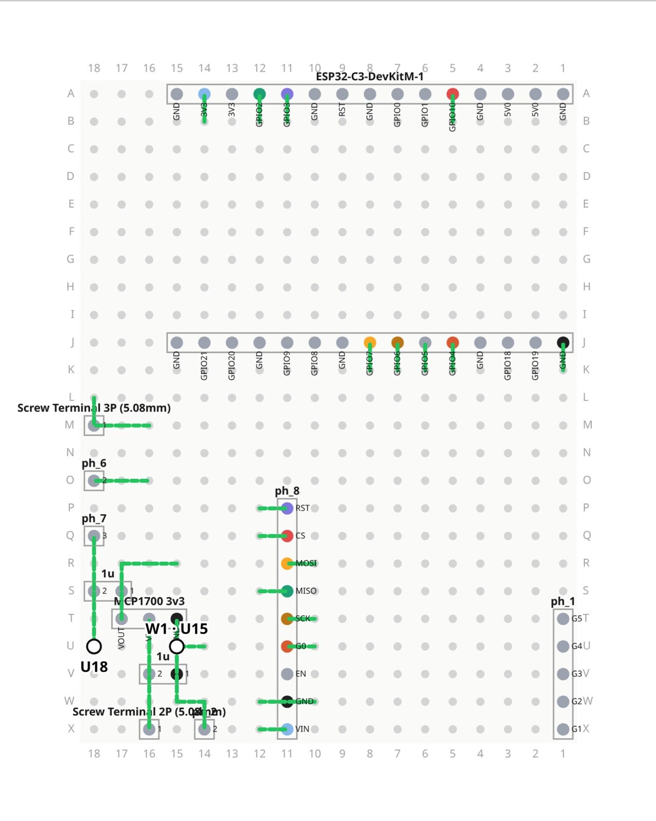
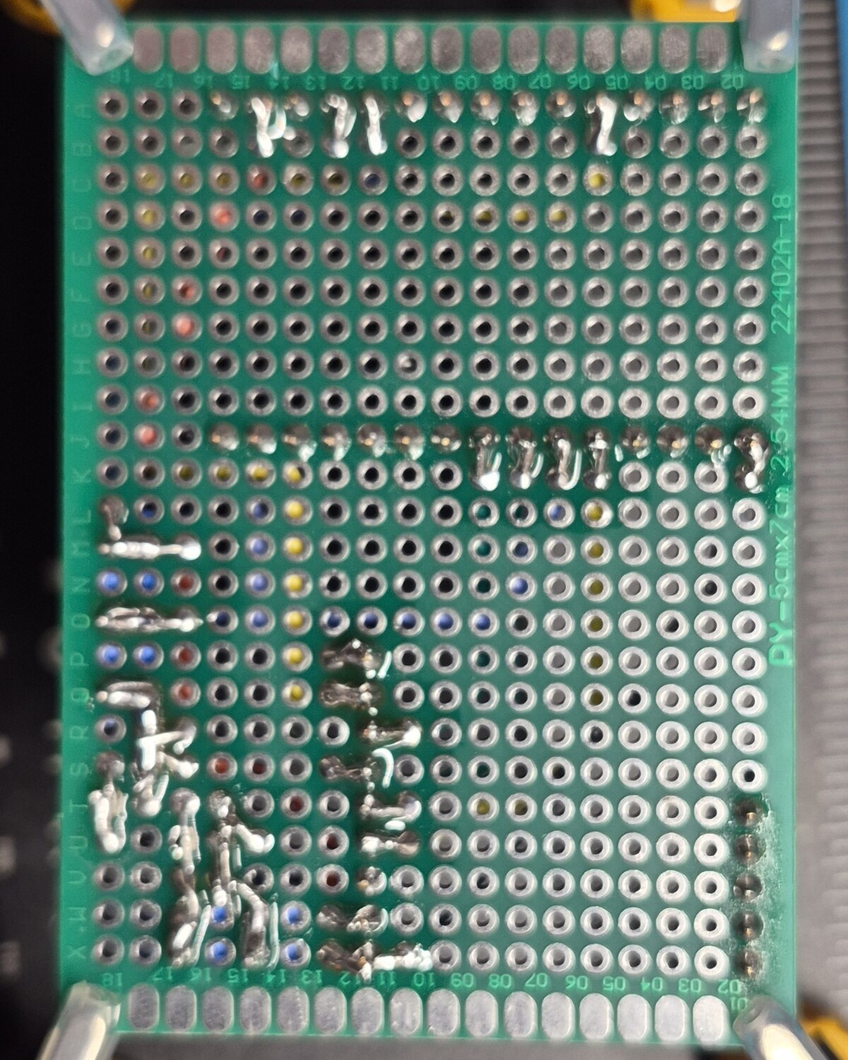
And check the datasheet for the pinout of every part before you solder it. Parts in the same package don't always share a lead order, and a tutorial's drawing may not match the part in your hand.
How a first build goes wrong
The same five mistakes come up again and again.
- A wire one hole off. The holes all look the same, and you're working on a mirrored view. Count from the board edge, not from the last part.
- A missed track cut. On stripboard, a strip you forgot to cut is a short. Make all the cuts before any part goes in, and tick them off a list.
- A part that doesn't fit. The pot is wider than you drew it, or the connector's pitch is off the grid. Test fit every part on the bare board before you solder the first one.
- Wires cut too short. A wire that's 2 mm short is scrap. Know each wire's length before you cut it.
- Running out of room. You start in one corner, and the last three parts have nowhere to go.
None of these are soldering problems. They're layout problems, and you can catch every one before the iron is hot.
I still make the first one. A lot. Even with a build guide open, I've put a wire in the wrong hole. The difference is that I had something to check the board against. I found it before I powered the board up, and before it damaged anything.
Plan the layout first
Graph paper works. Draw the parts at their real size in holes, draw every wire, then draw it all again mirrored for the solder side.
PerfBoard is the layout tool I built for this step. You place parts on a perfboard, stripboard or breadboard grid, say which pins connect, and route the wires and solder bridges.
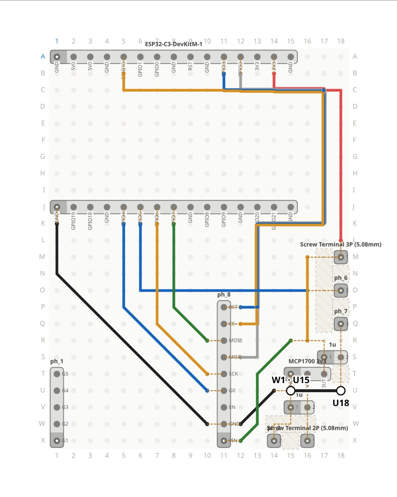
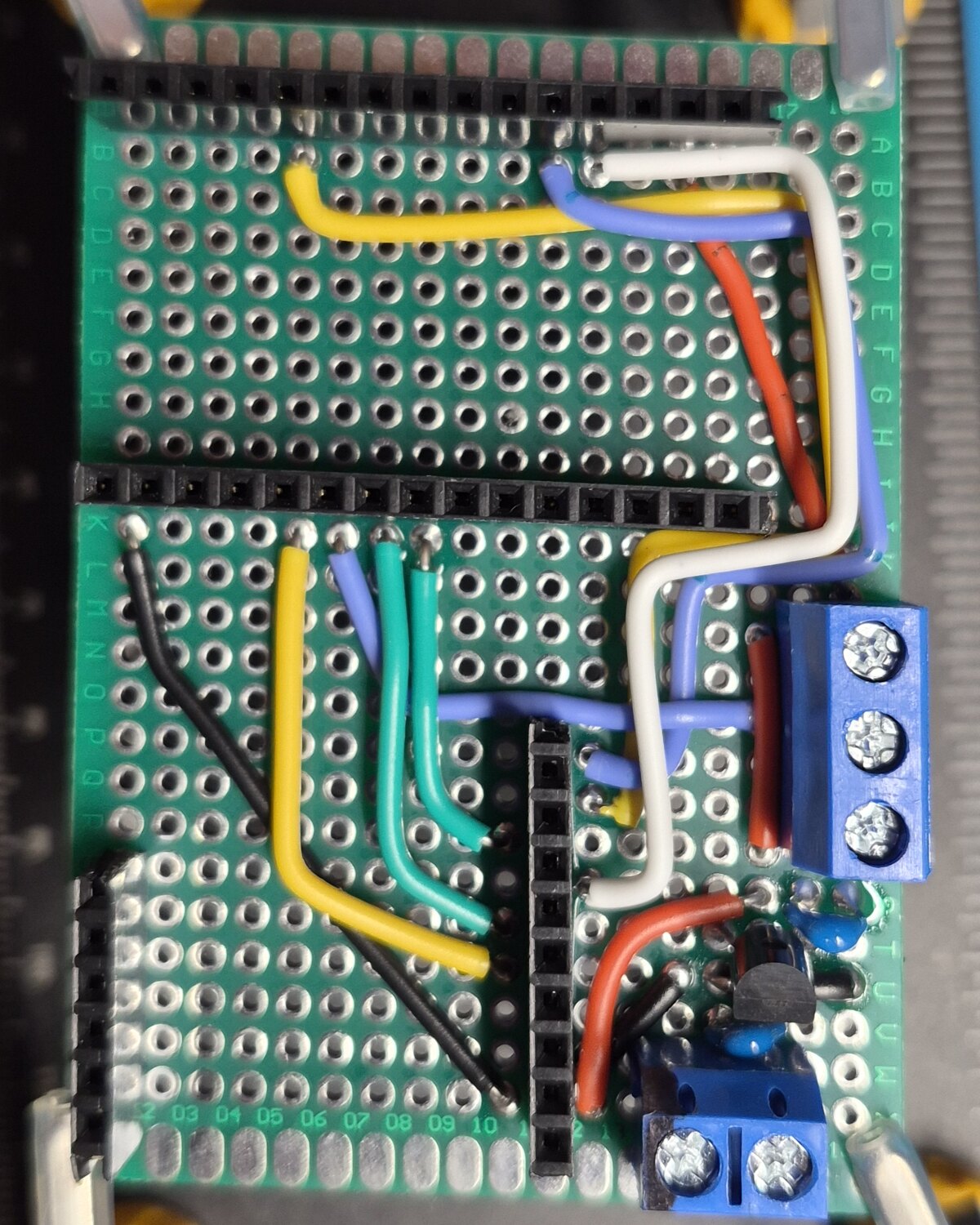
What you get back:
- Design rule checks. They run as you work. A short, overlapping parts or a connection you haven't wired yet shows up right away.
- A track cut list. On a stripboard, every track cut is listed strip by strip.
- Cut lengths and bend points. The cut sheet lists every wire with its measured length and where it bends.
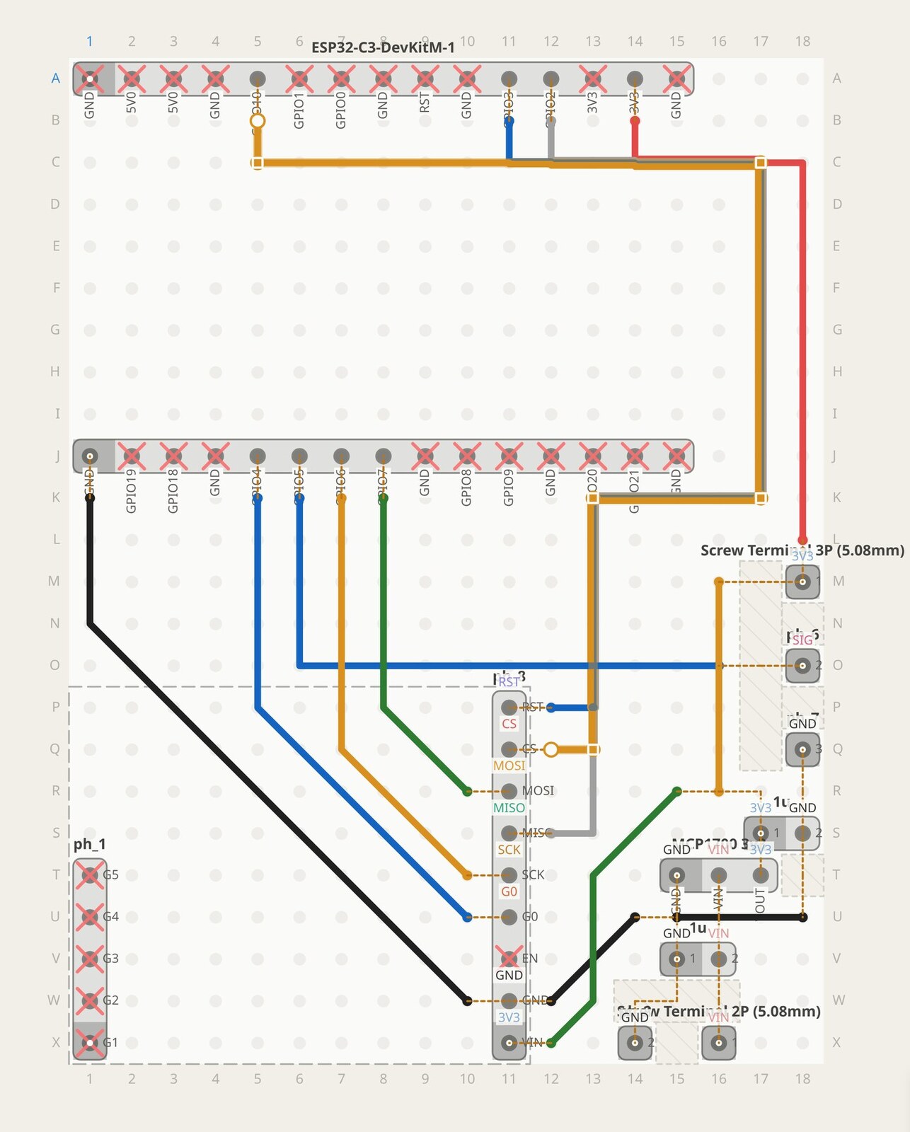
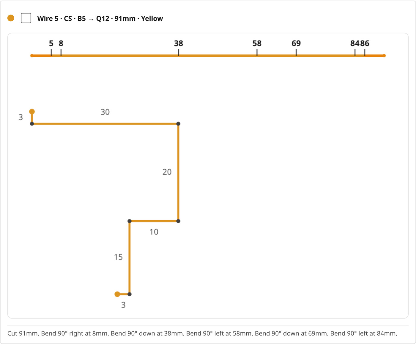
I trust these lengths. I cut and bend every wire before I assemble and solder anything, and it saves me a lot of time.
You can also simulate the circuit before you solder. That runs a model of what you drew, so it can't check that the real part's pins match the screen. Simulating, the full cut sheet and the PDF build guide are part of Pro.
Paper or software, the rule is the same. Make the mistakes on the grid, where fixing one takes a few seconds.
More articles
- Breadboard vs perfboard vs stripboard vs PCB: which should you use?
What breadboards, perfboard, stripboard and custom PCBs are each good for, the real trade-offs, and which one to pick for your build.
- From breadboard to perfboard to PCB: one sensor, three boards
One battery-powered LoRa temperature sensor, built three times: on a breadboard, on perfboard and as a custom PCB. What each stage is for.
Plan your next board on the grid before you solder, or start from one of the builds.